Solidworks Tutorials 17: Revolved Cut Feature
Revolved cut feature is one of the very useful solidworks feature tool, which helps to remove materials from 3D models possess axis symmetry. Revolved cut removes materials by revolving a closed profile a along an axis. You can access this solidworks feature from both command manager and menubar. Extrude cut feature also helps to remove materials from 3D models, but only in linear manner.
The revolved cut solidworks feature is main applications is helps to make axis symmetric models of train wheels, stepped shafts, curved holes, piston ring seating etc. In the upcoming tutorials posts, I will include the application of each solidworks feature 3d models. click here to see more solidworks tutorials for beginners
Checkout Best SolidWorks Training Materials here.
Let us learn how to use the revolved cut feature in solidworks.
How to Use Revolved Cut Feature
Here I am going create 3d cylinder with one end side internally stepped as shown in the figure.
The dimensions are rough and you can select any dimension as your comfort.
Note: This is just tutorial showing how to use revolved cut tool, not showing any product drawing or designing in it. If you are advanced SolidWorks user please avoid it. This Solidworks tutorial is for beginners, students or people likes to learn about SolidWorks.
Click here to Buy Advanced SolidWorks Tutorials from Amazon
Related SolidWorks Features Tools Tutorials:-
Step 1 : Create New Part File
Open the Solidworks by double clicking on the icon from the desktop. Then open a new part file for creating sketches. If you don’t know it, read how to create new part file here. Select any plane (e.g. front plane) and normalize using “Normal To” button. Also Read SolidWorks Heads-up Toolbar on this blog.

Step 2: Draw Reference Axis
Go to sketch and select the line or centerline sketch tool from the sketch command manager. First draw a line through origin of your drawing part. There is no dimension restriction for this centerline. Draw a long one. Click here to see how to use line sketch tool

Step 3: Sketch Profile for Cylinder by Revolved Boss/Base
Then you just create rough rectangle with one edge on the centerline as shown in the figure below. If you wish to give certain dimensions, use the smart dimensions from the sketch command manager.

Step 4: Use Revolved Boss/Base Feature
After sketching the rectangle, you just “exit the sketch”. Then go to feature command manager and click on the revolved boss/base feature. Select the axis line and then select the rectangular profile for creating 3d cylinder. To know more, Read How to Use Revolved boss/base feature

Step 5
Select the “front plane” from the Featuremanger design tree. Then click the mouse right button and click on the “Normal To” button.

Create a closed profile like on the below image.

Then exit the sketch and go to feature manager command manager. Select the “Sketch 2” in the Featuremanager design tree and select the “Revolved Cut” feature from the command manager.
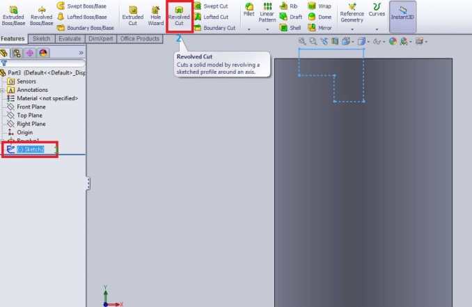
Here, I already drawn the profile through the centerline. So “Line 1@Sktech-2” automatically select as axis of revolution. You can see the preview of revolved cut feature in the below image.

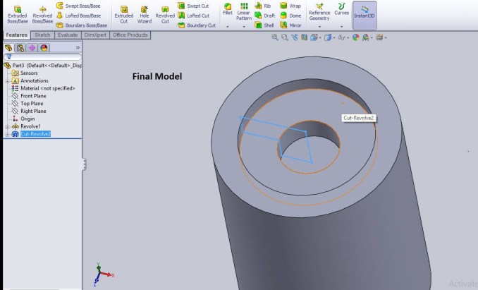
You adjust the revolution angle. Here I set “360 degree” for full revolution cut. Then click on the “green tick” button to complete the revolved cut.
The final image is shown below.
Sectional View

Related SolidWorks Sketch Tools Tutorials:-
Additional Info: Revolved Cut Property Manager

Axis of Revolution: This is reference axis which helps to revolve the sketch entity around it.
Direction 1 or 2: Here you can set the revolve cut type, reverse the direction and direction angle. The revolve types available are blind, up to surface, up to vertex, offset from surface and midplane.
Thin Feature: Here you can make thin revolve 3d models by setting small thickness. It contains one-direction, midplane and two-direction types available and also can revere the direction of thin feature application.
Selected Contours: If you have two or more closed contours around an axis. Using the selected contours, you can revolve the multiple sketches in one operation.
More Solidworks Tutorials are coming soon!
Feel free to share your honest opinions about this tutorial and follow on Facebook, Twitter and Googleplus.

Solidworks Heads Up View Toolbar

SolidWorks Spline Sketch Tool_SolidWorks Tutorial 35

I am currently studying HNC Mechanical Engineering, my background is in AutoCAD. Study has now moved onto Solidworks, which I have never used and has caused me much anxiety on how I would complete the assignment. Since discovering these tutorials, my angst levels have decreased as these are really helpful.
Thank you very much and keep looking for new solidworks tutorials.
Hi I am using solid works 2019 in this I need on help, when I creating hole table I selected the face on that time extruded cut feature also getting select but I need only a holes by this its take more time to delete this extruded cut feature column is there any setting to avoid that feature in hole table ?