SolidWorks Spline Sketch Tool_SolidWorks Tutorial 35
Hi friends, welcome to SolidWorks tutorials for beginners guide and in this tutorial, I am going to show you how to use SolidWorks spline sketch tool in CAD for creating complex curves. This is very basic how to tutorial, showing how to use this tool for sketch two or more pointed curves and also explains the spline property manager for controlling spline curve point co-ordinates, angle, relations etc. Below you can see about spline curve basics and how to use it in step-by-step SolidWorks CAD screenshots.
What is SolidWorks Spline Sketch Tool?
SolidWorks Spline is a sketch tool used to sketch or draw spline (curves) on the sketch graphics area. This sketch tool helps you to add spline points and join line between them. After that you can adjust the spline point positions, curve angles etc. Spline sketching tool is mainly used to create curves simple as well as complex. For creating a simple curve draw two spine points and adjust the line curvature as your requirement. You can use both mouse pointer and spline property manager to adjust tangent weighting, x-y co-ordinate positions and tangent radial angle. Checkout Best SolidWorks Training Materials here.
Main applications of SolidWorks spline sketching tool is that helps to create complex parts, easy to design products from the pictures, used for sweep boss or sweep cut feature applications, create complex structures etc.
Let us see SolidWorks step-by-step tutorial for using spline tool.
How to Use SolidWorks Spline Sketch Tool?
Here, I am going to show you how to create simple curve using the spline tool and also explains the spline property manager too.
Step 1: Create a Part File
Open SolidWorks CAD software. Click on the ‘New’ button from the quick access toolbar or from file menubar. From that, select ‘Part’ and click ‘OK’. Then you can see the Main user interface of SolidWorks modeling software.
File -> New -> Part -> OK

Select the default “Right Plane” from the Features DesignTree manager. Go to Heads-up toolbar and click on “View Orientation” and click on “NormalTo”. Then you can see the Top plane view changes from isometric to XY plane.
Step 2: Select SolidWorks Spline Sketch Tool
There are two options for selecting spline sketching tool in this CAD software and they are:-
Using Sketch CommandManager (Sketch toolbar)
Go to Sketch command manager and click on the Spline button like as shown in the below screenshot.

Also Read Solid-Works Features Command manager
Using Menubar
Move your mouse pointer to Menubar and Click on “Tools Menu”. From drop down menu, select “Sketch Entities” and click on the “Spline” from the appearing side drop down menu.

Step 3: Draw Spline Curves and Points
Now, your mouse pointer is changed to sketch pencil with spline on its suffix.
First, click on the right plane or origin to create first spline point.

Then, move to right or left direction and click on plane to create second spline point.

You can see a straight line. To make it to simple curve you need one more spline point between the 1st and 2nd spline points.
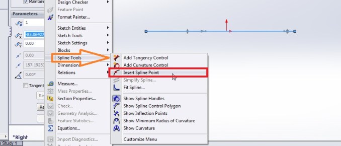
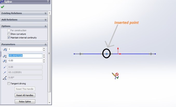
First, select the spline curve as sketched in the plane and go to “tools menu”; select “Spline tools” from the drop down menu and click on the “insert spline points”. Then it will create spline point between two of points a shown in below screenshot.
Related Tutorial: How to Use Solidworks Helix and Spiral Feature Command

Like that, you can add Tangency control, Curve control, simplify curve, show curve handles, show curve combs etc.
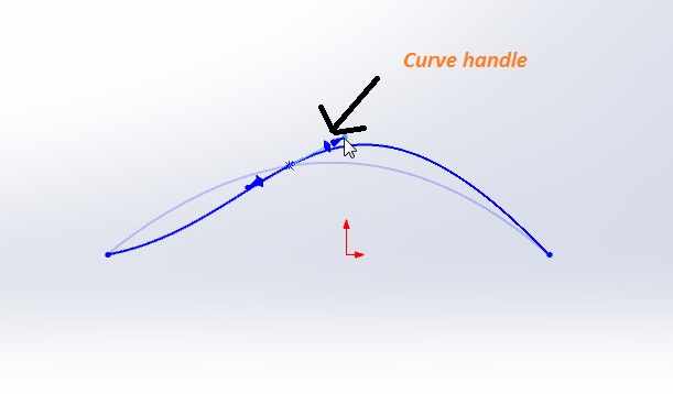
Curves handles help to shape the spline curve as per your requirement and an example is shown in the below screenshot:-
Simplify curve helps to smoothen the curve by deleting the intermediate spline points and apply tolerance for curve simplification.


The curvature combs enables to give idea about the curve smoothing and it helps to adjust the points for getting fine curves.
This way you can create simple spline curves using the SolidWorks spline sketch tool. Wait for my upcoming SolidWorks tutorials for advanced uses of spline sketching tool.
(banner)
Spline Property Manager

Existing Relations: it shows the exiting relation between two splines lines or curves.
Add Relations: It helps to add new relation such as coincident or tangency between another sketch profile and a spline curve.
Options: It contains options such as for construction, show curvature and maintain internal continuity.
Parameters:-
It contains parameters such as Spline point number, X co-ordinate, Y co-ordinate, Tangent weighting 1, Tangent weighting 2, Tangent radial direction, tangent driving, relax spline, reset the handle etc.
Spline point number: It indicates that the each spline points and automatically give numbers to them. For editing positions and tangent radial direction angle, just select the number of the point and do it from the spline property manager.
X-Y co-ordinate: Indicates the x-Y positions of the each select spline point number.
Tangent weighting 1 & 2: It indicates the tangent handles positions for a selected spline point.
Tangent Radial Direction: It is angle between the tangent handles and imaginary horizontal line (X axis).

SolidWorks Tutorial 23: Loft Boss or Base Features Tool

Solidworks Helix and Spiral Tutorial – Solidworks Tutorial 38

You are awesome! This is the best tutorial on this tool that I have seen!
Thank you so much for creating it:)
Thanks in favor of sharing such a good idea, piece of writing
is good, thats why i have read it completely