SolidWorks User Interface (UI)
SolidWorks is 3D solid modeling cad software which have very simple user interface (UI) with well placed tools positions and wide graphics area for designing purposes. The UI is very user-friendly and pleasing to eye with light grey background. It provide complete customization for the SolidWorks UI, that means you can arrange the tools, command bar, space of graphics UI etc as your needs. It is featured in speedy access of each tool through tool bar or just searches the first or two letters of tool commands in the command search bar. It helps to reduce the strain of your eye while designing and also increasing the productivity.
Table of Contents
SolidWorks User Interface Basics
There are 8 important sections contained in Solid works UI, which are listed in detail below with aid of images.
Watch our Video about SolidWorks User Interface Now:-
Checkout Best SolidWorks Training Materials here.
Menu bar
You can find the menu bar at the top most portion of the Solid works user interface. It contains some standard menu tools (New execution of files, Open, Save, Print, Select, Undo, Properties, Options and Rebuild), SolidWorks search, fly out menu help options and detailed SolidWorks side drag menu. See the Solidworks Menubar in Detail.

Command Manager
The command manager tool bar contains the most frequently used tools for designing process. It contains various sub-sections such as “Features, Sketches, Evaluate, DimXpert, Office products”. Each sub-section is arranged in tabbed manner. So, to access it, just click on the tab, it will automatically update with available tool services in the command manager.

If you don’t want to see the features icons, unpick the “Use the Large button with text from the toolbar dropdown or go to “Tools -> Customize”.
Features: It contains 3D solid addition and elimination tools like extrude boss/base, Revolve Boss/Base, Loft Boss/Base, Sweep Boss/Base, Boundary Boss/Base, Boundary Cut, Extrude cut, Revolved cut, Sweep cut , Loft Cut , Boundary Cut, Fillet, Chamfer, Simple Hole, Hole Wizard, Rib, Shell, Draft, Reference Plane, Linear Pattern , Circular Pattern, Mirror , Helix and Spiral Curves , SheetMetal etc. To see more about SolidWorks Features Tools
Sketch: The Sketch tools help to make 2D drawing before creation of 3D model. You can draw any view (Top/Side view) of the product and use the feature options to add materials. Sketch tools are Line, Circle, Rectangle, Polygon, Arc, Slot, Ellipse, SmartDimension, Parabola, Sketch Fillet, Sketch Chamfer, Sketch Trim Entities, Linear Sketch Pattern, Circular Sketch Pattern , Spline etc.
Evaluate: These tools helps to analyze the design and contains tools like Geometry, Draft, Undercut, Parting line analysis etc.
DimXpert: It is dimension agent of Solid Works, which enables to dimension and tolerance to your modeled part.
Office Products: Other supporting packages like Simulation, Routing, PhotoView360, Circuitworks etc.
FeatureManager Design Tree
The feature manager design tree helps to see how you construct or design the model. It shows your sketch 2D files, Feature Tools, planes etc. From there, you can directly access through the each tree function from the user interface for editing purposes. Overall it gives an outline about the model development. You can also filter the design tree by types of feature tools, Sketches, Mates, folders etc.
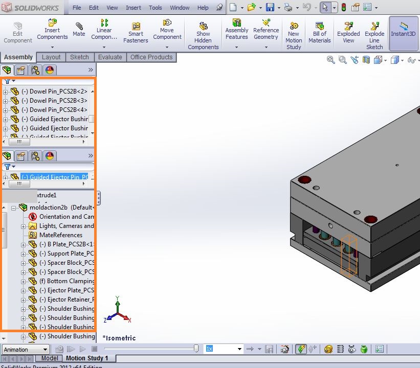
Configuration Manager
It manages the different configuration of part or assembly in a design document. You can select, create and view multiple configurations using it. Also you can control the display states of part file by linking display states to configuration.

Property manager
The property manager controls the all tools properties of Solid Works. When you click any tool button on the command manager, the property manager automatically appears and asks for the value or property entry. You need to enter or select the correct property values, otherwise it rejects the entry.

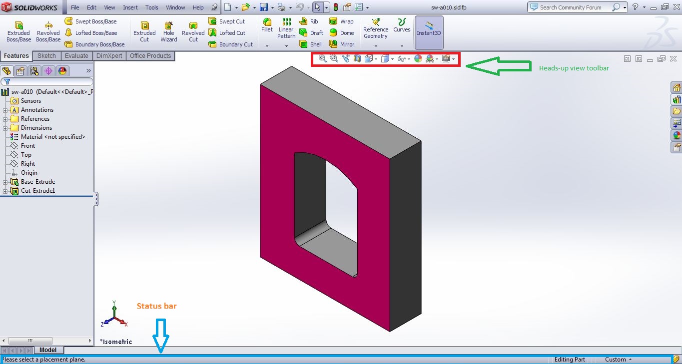
Graphics area
This is the working area of SolidWorks in which you can draw or create 3D models of different products. It shows the display of parts or assemblies here. Here you can see a XYZ co-ordinate ate bottom left corner of graphics area. These trimetric coordinates convert the graphics area into three dimensions.

Heads-up view Toolbar
It contains the different view tools of model such as Zoom, Sections, and Geometrical orientation view. It is normally found inside the graphics area at the top-center position. Each view buttons contains side drop down menu, contains various related view options.
Status bar
It provides live information about the current working feature used in Solidworks user interface. It lively shows the mouse pointer movements, sketch status, co-ordinate information’s, commonly used measurements etc.
Overall
The SolidWorks User interface is very simple to operate and all main tools can access directly without any previous knowledge of accessing them. But, to use the each feature, you must know about the functions and capabilities of such tools. In my next article you will see each toolbars individual tools icons, functions and short key for accessing each of them. To get more information , click here
Feel free to express your opinions and tips in the comment box. Thanks for reading.

SolidWorks Tutorials 10: Parabola Sketching

SolidWorks Tutorial 12: Sketch Chamfer Tool

Good one! Keep posting more solidworks tutorials.