SolidWorks Tutorials 2: Line Sketching Tool
Do you know about the Line sketching tool in SolidWorks? It is one of the useful sketch tool which helps to prepare the 2D drawing of a product or part in graphics interface. The Line tool provide full freedom to start the drawing anywhere on the graphics area and very simple to use. That means no complex process is needed to use the Line sketch tool in SolidWorks.
Line is one of the first sketching tools in command manager which helps to draw lines in horizontal, vertical or at any angle. While drawing the pointer shows the distance between each h lines points according your selected standard measurement settings. Also shows the angle measurement while drawing the angle lines. This measurement information will helps to draw rough sketch around the dimension of your actual drawing.
In line tools side down drag menu, contains “Centerline” tool, which enables to draw centerline in 2D sketch drawing. It follows the engineering graphics rule representation and useful in case of revolving boss or cut features.
Midpoint line is new addition of Line sketching tool in the SolidWorks sketch cpmmand manager which helps to create midpoint line on the graphics area. when you click on the interface, line starts from the center and lengths both sides while dragging the mouse.
Note: This is just tutorial showing how to use line tool, not showing any product drawing or designing in it. If you are advanced SolidWorks user please avoid it. This Solidworks tutorial is for beginners, students or people likes to learn about SolidWorks.
Checkout Best SolidWorks Training Materials here.
Table of Contents
How to Use Line Tools in SolidWorks
For using any Sketch tools of SolidWorks, some basic operations you must follow in especially in Part drawing.
Watch our Video about Line Sketching:-
Step:-1:-
Open the SolidWorks from your desktop, by double clicking or use right mouse button and from drag menu click “Open”. Now SolidWorks main user-interface will appear.

Step-2:-
Click on the “New icon” from the standard toolbar or click one “File” menu and select the “New”. Then a dialogue box will appear and contains “Part”, “Assembly” and “Drawing”. You select the “Part” and click “ok”.
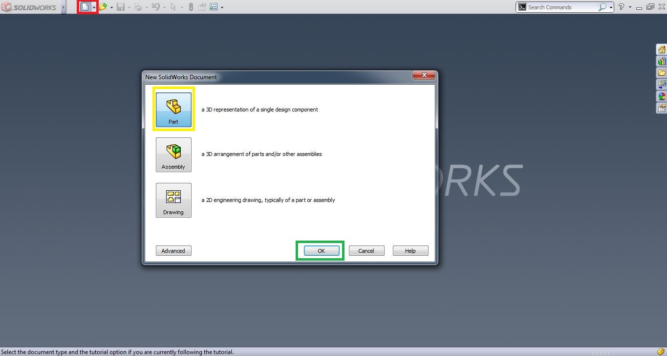
File -> New -> Select Part -> Ok.
Step-3:-
It will open new part file interface with all tools and menus. From the Feature Manger Design Tree, Select the “Plane” for starting your drawing. Without selecting the plane, you can’t draw anything in graphics area. So, it is necessary thing before drawing part file.
You have 3 plane options available, which are Front Plane, Top Plane and Right Plane. You must select any plane to start designing process in SolidWorks.
Note: Step-1 to 3 is basic procedure for opening New Part file, before drawing.
Here, Select “Top Plane” for showing the tutorial purposes.

Here plane have Trimetric or 3D view. You can possible to start 3D sketch on this plane, if you are an advanced or professional user. For beginners, it will better to normalize to understand or easy sketching. Read Heads-up toolbar on this blog.
From the Feature manager Design Tree, click the right mouse on the selected “Top Plane”. Then a drag menu will appear and from the menu options click on the “Normal To” button, which is represented below.

Then the plane will looks towards to you or looks like 2D (XY plane). Now you can move to select the Line tool.

Step-4:-
From the command manager, select the “Sketch” tab. From their click on the “Line” button and it is represented below.

Alternative Way to Select Line Tool
From menu bar, click on Tools menu button and drop down menu will appear. From the drop menu, select the “Sketch Entities” and side drag menu will appear. From it select the “Line”.
Tools menu -> Sketch Entities -> Line
Now, you select the Line sketch tool and drag your mouse pointer to the SolidWorks graphics area to start drawing. Now, the mouse pointer will looks like Pencil with Line symbol as shown below.

Step-5:-
Now, you can click anywhere on the graphics area and drag your pointer in any direction to draw line and a gain click the mouse left button to complete the one line. This way you can draw infinite number of lines here. To stop with the line drawing, double click on the mouse pointer.
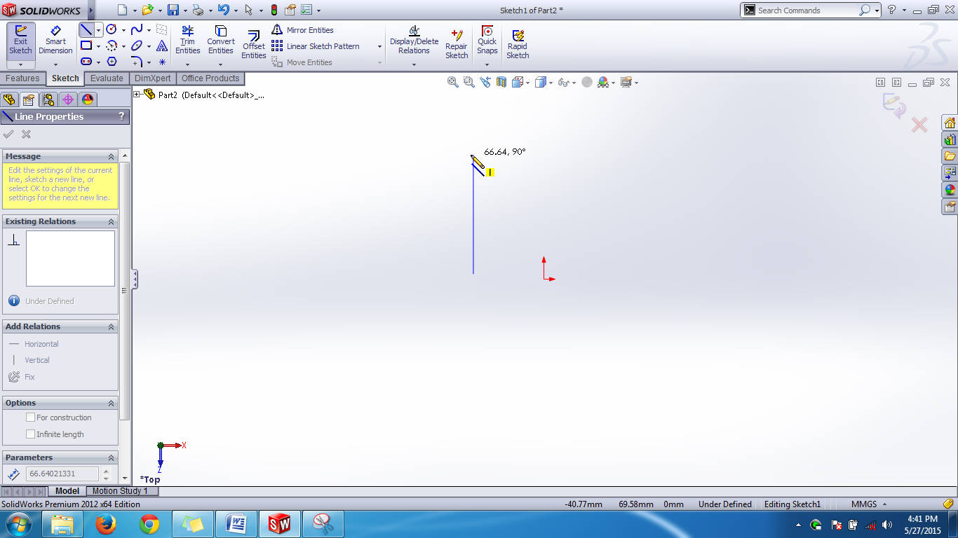
In the property manager menu, Line Properties control will appear. You can control the line sketch after the rough drawing done, through the Line Property manager.
Related SolidWorks Sketch Tools Tutorials:-
Line Property Manager
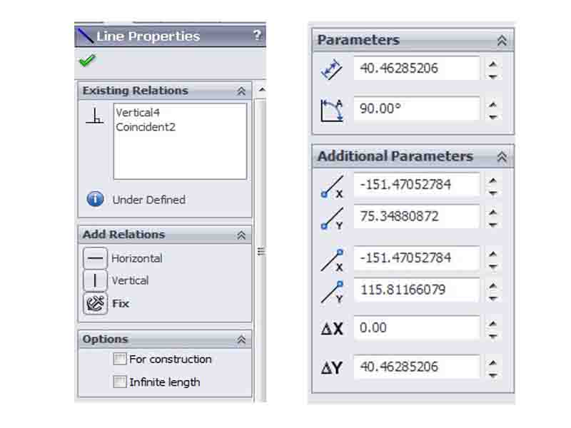
Existing Relations
This shows the existing relation of your line sketch as your selected currently. If you draw line horizontally in graphics area, shows Horizontal with line no. (e.g. Horizontal2).
Add Relations
This is helps to add new relations to your Line sketch. It contains relations like horizontal, vertical and Fix button. If you want to convert your horizontal line to vertical, you just select the line and add relation from it.
Options
It contains two options such as “For construction” and “Infinite length”. If you want to represent a line under construction representation, just tick on the “For Construction” option. The infinite length converts your line infinitely long as in the drawn direction (both opposite sides).
Parameters
You know that line is constructed between two points in certain distance. The parameters section controls the line length and angle orientation in the graphics area.
Additional Parameters
It controls the each points X-Y co-ordinates measurements and position.
How to Use Center Line Sketching Tool
Center line sketching tool is another Solidworks sketch feature which helps top create center line (usually represented as dot and small line together in engineering graphics). It divides a single part into two equal parts and helps to design a product according to it. It is very helpful in the creation of revolves features and symmetrical parts.
How to Select CenterLine Tool
There are two ways to get center line sketching tool and they are :-
From Sketch Command Manager
Go to sketch command manager and click on the Line sketching tool down arrow. from the drop-down menu, select the “Center Line”.

From Menubar
Go to “Tools” and select “Sketch entities” from the drop down menu. Then, you will side drop down menu and select “Centerline” from it.

Draw CenterLine on SolidWorks Graphics Area
After selecting the centerline sketch, go to graphics area and click on the point where you need the line starting and drag it using mouse. It is same as Line Sketching tool.

How to Use Midpoint Line Sketching Tool
Midpoint line is also a line which starts from the center and extends to both sides equally. If you want to create equal line from the center of a part, you can use the midpoint line sketching tool. Here, you will see how to use in SolidWorks CAD software.
How to Select Midpoint Line Tool
There are two ways to get Midpoint line sketching tool and they are :-
From Sketch Command Manager
Go to sketch command manager and click on the Line sketching tool down arrow. from the drop-down menu, select the “Midpoint Line”.

From Menubar
Go to “Tools” and select “Sketch entities” from the drop down menu. Then, you will side drop down menu and select “Midpoint Line” from it.

Draw Midpoint Line on SolidWorks Graphics Area
Select the center point of part (e.g: center of line) as the starting point of mid point line and drag the mouse sidewards. Then, you can see the midpoint line extending towards both sides equally. This line have three points such as two end points and one midpoint.

Miscellaneous
Top Plane Feature menu
You can access this menu by clicking right mouse button on the “Top Plane” option in the FeatureManager design tree interface.
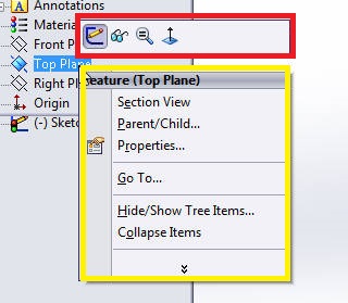
The menu contains split into two parts such as quick access buttons and other related menu options.
The quick access buttons contains Hide/Show, Zoom to selection and Normal To. The next part of menu contains 3D sketch on plane, Section View, Parent/Child and Customize.
Hide/Show: It will shows the plane information on the drawing plane. If you don’t want to plane information you can hide by clicking on this button. To show it, again click on this button.
Zoom to Selection: It helps to zoom the plane selected parts.
Normal To: Convert 3D to 2D view.
3D Sketch on Plane: You can directly make a 3D sketch drawing on the selected plane.
Section View: To see the sectional view of drawn part. It is useful in very complex parts designing jobs.
Parent/Child: to see the parent plane and child planes.
Customize: It helps to customize the menu with useful options display.
Overall
SolidWorks Line sketching is one of the easiest jobs for drawing part files. This article covers the how to use the line sketching tools with images and also explains the line properties and design tree plane menus.
Feel free to comment me your honest opinions and also inform me if any small information I forgot to write in it. Thanks for reading and I hope enjoy the SolidWorks Tutorials about Line Sketching.

Solidworks Tutorial 19: SolidWorks Swept Cut Features Tool

SolidWorks Command Manager: SolidWorks Sketch Toolbars
