Revolved Boss or Base is a SolidWorks feature tool which is used to create solid 3D model around an axis. You can revolve the sketch around an axis to add materials to it. You can access revolved boss/base from both command manager and menubar. Like the SolidWorks extrude boss/base feature, you can also add materials in one or two directions, while revolving it. Click here to see more SolidWorks tutorials.
Using this feature, you can create solid rings, hollow cylinders, pressure vessels, solid and hollow spheres, power transmission pulleys etc. You see the applications of each feature in our upcoming tutorial posts. Now you can see the hollow cylinder creation exercise using Solidworks revolved boss/base feature.
The important thing to apply this solidworks feature tool, you need to draw a base reference axis for revolving.
Note: This is just tutorial showing how to use revolve boss or base tool, not showing any product drawing or designing in it. If you are advanced SolidWorks user please avoid it. This Solidworks tutorial is for beginners, students or people likes to learn about SolidWorks.
Go to the sketch and select line or center line. I prefer centerline sketch tool, because it is look like centerline engineering graphics representation and also used as axis. Select it from command manager and draw centerline of any length, vertical or horizontal. It’s up to you.
To create a hollow cylinder, you need to revolve a rectangle around an axis. The “OD, ID and L” dimensions are given below. Draw rectangle by using rectangle or line sketch tool and use smart dimension to make it in proper size.
Hollow cylinder thickness (t) = OD – ID = 50 – 30 = 20 mm.
Select the sketch from the featuremanager design tree. Here I select “Sketch-1”.
From command manager, you can select the Revolved Boss/Base button is look like this
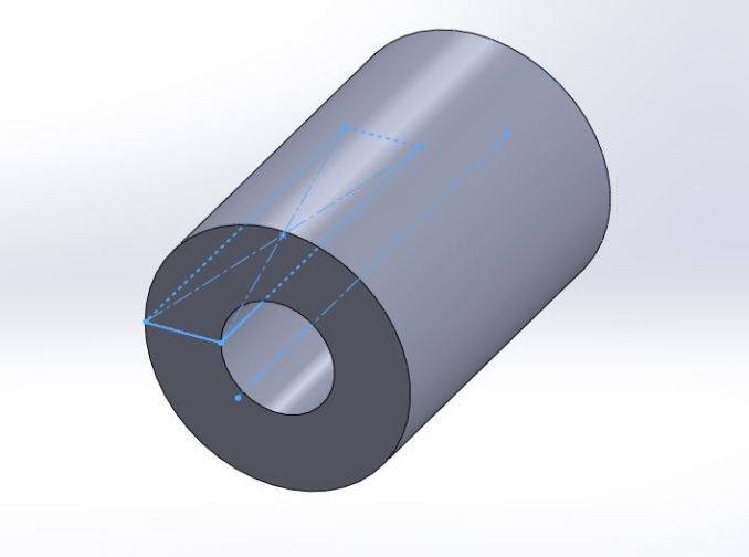
Here you see the revolved boss or base property manager with Sketch-1 in the below image.
You need to select the Axis of revolution in the blue area by clicking on axis line using mouse pointer. Then a preview of your revolved sketch will appear in yellow color.
In Direction 1, you can control the material adding direction. Here I select “Blind” and angle is 360 degree to make hollow cylinder. Click Green Tick button (OK) in property manager to complete the 3D drawing of hollow cylinder.
See Example Video:-
Additional Info: Revolve Property Manager
Axis of Revolution: This is reference axis which helps to revolve the sketch entity around it.
Direction 1 or 2: Here you can set the revolve type, reverse the direction and direction angle. The revolve types available are blind, up to surface, up to vertex, offset from surface and midplane.
Thin Feature: Here you can make thin revolve 3d models by setting small thickness. It contains one-direction, midplane and two-direction types available and also can revere the direction of thin feature application.
Selected Contours: If you have two or more closed contours around an axis. Using the selected contours, you can revolve the multiple sketches in one operation.