SolidWorks Tutorial 24: Loft Cut Features Tool Tutorials
Welcome to Solidworks Tutorial for beginners and today, you are going to see the Solidworks Loft cut features tool step-by-step tutorial and how to use them to create various models and shapes. This tutorials post shows the basic uses of SolidWorks Loft Cut features and you can apply this feature by following the same step explained below for creating new designs. Before going to SolidWorks Step-by-step tutorial, let us see small description about the Loft Cut tool. Checkout Best SolidWorks Training Materials here.

Related SolidWorks Tutorials:-
What is Solidworks Loft Cut Features?
Loft cut is a Solidworks features tool which helps to cut or remove materials between two or more profiles. It is just like Loft Boss or Base tool, but main difference is that Boss feature used to add material between profiles and Loft cut used to remove materials between them. It is also have property manager called as “Cut-Loft property manager”, using this you can control the various loft cutting of materials between profiles. The various methods used for loft cutting are Profiles method, Start/End Constraints, Guide Curves, Centerline parameters and Thin Feature methods. You can also find the Loft Cut feature tool in both features command manager and the “cut” section of Insert menu.
For applying Solidworks Loft Cut feature you should have 3D model or shape (say rectangle box), by using rectangle sketch tool and Extrude boss feature.
Let us see using the profiles methods of Loft boss/base, how to create model in Solid works.
How to Use Solidworks Loft Cut
In this tutorial I am going to use The Loft Cut using the Profile methods. The mainly used tools are Rectangle & Circle sketch tools, Reference geometry, Extrude boss and Loft Cut features tools also. The Smart Dimension tool is used to set the sketch profiles dimensions.
Step 1: Create Part File
Open the Solid Works and New part File. If you don’t know it, read how to create new part File. Select the Plane (e.g. Top Plane) and normalize using the “Normal To” Button.
Step 2: Make Solid Rectangle
For applying Loft Cut, you should need profile having some material, because of the application of this tool. For that you need to make solid rectangle box having size 100 x 80 mm. It is achieved by using the sketch user interface of solid works.
Select “Top Plane” and draw a Center rectangle in it. Using the SmartDimension tool, set dimension to 100 x 80 mm, is shown below. For easiness of view, I just convert the view into Isometric View using the “View Orientation” tool contained in the Solidworks Heads-up toolbar.

Using the Extrude Boss or Base feature you can make it into solid 3D rectangular box. Set the Extrusion distance is “70 mm”.

Step 3: Create Reference Plane for Second Profile
Here I am going to create circular profile on the top of the Rectangular box having distance is “0.5 mm”. Checkout this link to see How to Use Reference Plane Solidworks Tutorials for creating new planes on a surface.

Normalize the new plane (Plane 1) using “NormalTo” option and create circle profile having 50 mm circle diameter using the Sketch command manager tools. Then convert to Isometric view.

Exit the sketch area and go to features command manager.
Step 4: Locate Loft Cut Tool
From Command manager

Or
From Menubar

Go to Insert Menu section in Menubar and select the “Cut”. Then you can see side drop down menu and from that select “Loft Cut” feature.
Step 5: Apply Loft Cut to Profiles
Click on the Loft Cut feature button either from command manager or insert menu. Then you can see the Cut-Loft property manager.

You have to use the “Profiles” section of the loft property manager. Then click on the “Sketch 4 and sketch 2<5>” from the Featuremanager design Tree.

You can see the Loft lines connection between two profiles as you created in earlier steps.
You can direct the guide lines using the two green points in each profile by dragging it and its preview is shown below.

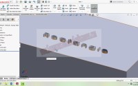
And click green tick button to confirm your action. Then you can see the loft cut body between circle and rectangle 3D box profiles. It removed material in such a way that circle is joined to the rectangular profile which is shown below.
Section view

This way you can use the Solidworks Loft Cut Features tool for cutting the materials between two profiles. You can use the other methods to loft cutting of materials in very complex shapes. I will also update the loft cut tutorial post by adding the uses of other methods contained in the Cut-Loft property manager.
Lofted Cut SolidWorks Tutorial: Profile Method
Lofted Cut SolidWorks Tutorial: Guide Curves Method
The Lofted cut Solidworks tutorial guide curves method helps to create complex shaped 3d models by adiing the material between two different sketch profiles through the guided curves. You can draw the different closed sketch profiles and also draw the guide curves using the spline sketch tools. Watch the video to learn guide curves method easily.
Lofted Cut SolidWorks Tutorial: Centerline Method
The Lofted cut solidworks tutorial centerline method helps to create complex 3d models with two different sketch profiles by directing the centerline or curves. You can watch the below video to learn the centerline method.
To get more How To Tutorials, Follow me on Facebook, Twitter, GooglePlus and YouTube.
Feel free to ask any doubts or questions about this Solidworks tutorials and thank you friends.

SolidWorks Curves Split Lines – Silhouette| SolidWorks Tutorials 42
SolidWorks Emboss Text | SolidWorks Tutorials 40

Sir is it possible that I can sketch two profiles in two different planes and perform loft cut. Both profiles are different in shapes. Please help
for performing cut feature, there should be some materials on the body or model. If you have it, you can create two sketches in both sides and perform loft cut.