Standard Mate Parallel Assembly | SolidWorks Assembly Tutorial-4
Welcome to SolidWorks Assembly tutorials for beginners and in this assembly tutorial, you are going to learn how to use standard mates for assembling two components. In this example, only showing how to apply parallel standard mates. If you missed to learn assembly basics, follow the below links.
1. How to Insert Part File to Assembly
2. Fix or Float Components in Assembly
3. How to Apply Standard Mate Concentric and Coincident
Note: This tutorial is completely for SolidWorks beginner level people.
Let us starts to learn SolidWorks assembly using the standard mates features.
How to Use Parallel Standard Mate
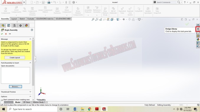
Open the SolidWorks and Select “New”. From the pop-up menu, select the “Assembly” file and you will get new assembly graphics interface as shown below.


Insert Design Components
For showing the parallel standard mate, going to use the SolidWorks library parts (already designed standard parts). So, let us learn how to insert library parts to assembly.
Go to “Design Library” and click to open it.
From the Appearing dialogue box, you have to select “Toolbox” and also select the one of the standard dimension from the list. Here, selecting the “ANSI Metric”.

You can select the required standard model parts like bolts and nuts, washers, bearings etc.
For showing the parallel standard mate. Selecting one bolt and nut.

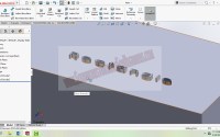
Also made a rectangle model with holes as shown below.

Insert the box model and fix it. And also apply Float condition to the Bolt model.

Note: Always insert the base part into assembly interface and fix it on the origin. It will help you to apply geometric relations between them.
(image)
Apply Parallel Standard Mate
Next step is to apply parallel standard mate. That is need to make one face of box parallel with bolt face.
For that, apply Concentric standard mate for make it align with hole axis.

Then select the bottom face of the bolt and select top face of the box as shown in figure above.
After applying mate, it will look like in below image.

Now, it’s time to make one face of the bolt head parallel to the one of the face of the box.
For that, activate “mates” feature and select one face of the bolt and face of the box as shown below. The parallel standard mate automatically applies to the model.

This way you can apply parallel standard mates in SolidWorks assembly model.
Save the assembly and will be useful in studies of the other features of assembly.
If you found this SolidWorks Tutorial useful, feel free to share to friends, like and comment. Thank you friends.
Learn more about assembly, click here

SolidWorks Tutorial 18: Swept Boss or Base Feature

SolidWorks Tutorial 9: Ellipse Sketching Tool